When it comes to characterizing laser beams, there are several types of cameras that can be used, each with its own advantages and disadvantages. Some of the most common types of cameras used for laser beam characterization include:
CCD Cameras (Charge-Coupled Device): These are cameras that use a CCD sensor to capture images. CCD cameras are sensitive to a wide range of wavelengths and are capable of capturing high-resolution images. They also have low noise, high dynamic range, and good color reproduction. CCD cameras are commonly used in laser beam profiling and other types of beam characterization.
CMOS Cameras (Complementary Metal-Oxide-Semiconductor): These cameras use a CMOS sensor to capture images. CMOS cameras have similar capabilities as CCD cameras but are more cost-effective, have lower power consumption, and can be built in smaller form factors. They are also useful for fast imaging and high-speed applications.
The spectral sensitivity curve of HUARIS ONE profiler is presented in the graph below:
ICCD Cameras (Intensified Charge-Coupled Device): These cameras use a CCD sensor and an image intensifier to capture images. ICCD cameras are sensitive to low-light conditions and can be used to capture images of laser beams with very high power. They are commonly used in high-power laser applications, such as laser cutting and welding.
InGaAs Cameras: These are cameras that use a InGaAs sensor, a specific type of sensor that is sensitive to the near-infrared (NIR) wavelengths, which is a common region for laser applications. These cameras can be useful for measuring high-power beams in the NIR region, and are commonly used in fiber-optic communication, spectroscopy and other related applications.
SWIR cameras (shortwave infrared): These cameras are sensitive to the shortwave infrared (SWIR) wavelengths, which is another common region for laser applications. These cameras are useful for measuring high-power beams in the SWIR region, and are commonly used in sensing and imaging applications.
The best camera for laser beam characterization will depend on the specific requirements of the application, such as wavelength, power, and spatial resolution of the laser beam, as well as the environment the camera will be used in. It’s important to consider factors such as cost, size, and ease of use when selecting a camera for laser beam characterization.
CMOS (Complementary Metal-Oxide-Semiconductor) and CCD (Charge-Coupled Device) are two different types of image sensors that can be used in cameras, including those used for laser beam characterization. Both types of sensors have their own advantages and disadvantages, and the choice between them will depend on the specific requirements of the application.
CCD sensors are known for their high image quality and low noise, they are sensitive to a wide range of wavelengths and are capable of capturing high-resolution images. CCDs are also capable of capturing high dynamic range images, and have good color reproduction. They are commonly used in scientific and industrial applications where high image quality is needed. However, CCDs are generally more expensive than CMOS sensors and have higher power consumption.
CMOS sensors, on the other hand, are more cost-effective than CCDs and have lower power consumption. They can also be built in smaller form factors, making them more suitable for portable or compact applications. They are also useful for fast imaging and high-speed applications, and their technology allows for more integration on chip, such as the addition of a processing unit that can reduce the need for external components. However, CMOS sensors can have higher noise levels and lower quantum efficiency (QE) than CCDs, which means they may require additional processing to achieve similar image quality as CCDs.
In summary, CCDs are better suited for applications that require high image quality, while CMOS sensors are better suited for cost-sensitive applications or those that require low power consumption and compact form factor.
As for the use in the laser applications, CMOS arrays are believed to have higher damage threshold than CCDs.
It’s worth noting that the choice between CMOS and CCD sensors is not always clear cut, and it’s important to consider the specific requirements of the application, such as wavelength, power, spatial resolution and data rate, as well as other factors such as cost, size, and ease of use.
Check the specification of Huaris laser beam profilers
When it comes to selecting a detector array for laser beam characterization, there are several options available, including black and white (monochrome) arrays, and color arrays. The choice between them will depend on the specific requirements of the application.
Black and white detector arrays are sensitive from ultraviolet, through visible to near-infrared (NIR) spectrum spectral area. They are commonly used in laser beam profiling and other types of beam characterization, as they can provide high spatial resolution and good sensitivity. They are less affected by ambient light and can be more sensitive to the laser radiation.
Color detector arrays, on the other hand, are sensitive to multiple wavelengths of light at a time, typically in the visible spectrum, and can capture information about the color of the light. They are commonly used in applications where color information is important, such as in color imaging, material analysis, and color sensing. They can provide more information about the laser beam but can be more affected by ambient light. On the other hand, they have poorer spatial resolution, for this reason they are hardly used in the laser beam characterization where demand for high accuracy of the intensity mapping is crucial.
The choice between a black and white detector array or a color detector array will depend on the specific requirements of the application. If the color information is not important for the application, a black and white detector array can provide a better sensitivity and spatial resolution, while if color information is important a color detector array should be used. Additionally, the environment where the detector will be used should be taken into consideration, as color detector array can be more affected by ambient light.
When it comes to color detector arrays, the color depth and the analog-digital converter (ADC) used in the camera can affect the overall image quality and the ability to accurately measure the laser beam.
Color depth, also known as bit depth, refers to the number of bits used to represent the color of each pixel in an image. The higher the color depth, the more colors can be represented, and the more accurate the color representation will be. A higher color depth also allows for a greater dynamic range, which is the range of brightness levels that can be captured in an image. A higher dynamic range allows for more accurate measurements of the laser beam.
Analog-digital converter (ADC) is a circuit that converts an analog signal into a digital representation of that signal. The ADC in a camera converts the analog image signal captured by the sensor into a digital image. The ADC resolution, measured in bits, determines the maximum number of digital values that can be produced by the converter. A higher ADC resolution will result in a higher color depth, which allows for more accurate color representation and dynamic range.
The color depth and ADC resolution of a camera will affect the ability to accurately measure the laser beam. A higher color depth and ADC resolution will provide more accurate color representation and dynamic range, which allows for more accurate measurements of the laser beam.
It’s worth noting that the color depth and ADC resolution are not the only factors that affect the image quality and measurement accuracy, other factors such as the sensor quality, the lens, and the optics also play a role.
Pixel size and pixel pitch are two related but distinct characteristics of image sensors, such as those used in cameras for laser beam characterization.
Pixel size refers to the physical size of each individual pixel on the image sensor. It is typically measured in micrometers (µm) and can range from a few micrometers for high-resolution sensors to tens of micrometers for lower resolution sensors. A larger pixel size generally means that each pixel can collect more light, which can result in higher sensitivity and a higher signal-to-noise ratio (SNR).
Pixel pitch, on the other hand, refers to the distance between the centers of adjacent pixels on the image sensor. It is typically also measured in micrometers (µm) and can range from a few micrometers for high-resolution sensors to tens of micrometers for lower resolution sensors. Pixel pitch is inversely proportional to the resolution of the sensor, meaning that a smaller pixel pitch results in a higher resolution sensor, and vice-versa.
Finer pixel size allows fitting a greater number of pixels in a given physical area allowing increase of an array effective resolution.
In summary, pixel size and pixel pitch are related but distinct characteristics of image sensors. Pixel size refers to the physical size of each pixel and can affect the sensitivity and SNR of the sensor. Pixel pitch refers to the distance between adjacent pixels and can affect the resolution of the sensor.
Both pixel size and pixel pitch are important characteristics to consider when selecting an image sensor for a specific application, and the best choice will depend on the specific requirements of the application, such as the resolution, sensitivity, and dynamic range needed.
As a general conclusion, where spatial resolution is more important than smaller pixel size should be selected. On the other hand, when sensitivity is critical, then the greater pixels will perform better.
Huaris One products are designed for higher sensitivity. Their pixel size is 5.2 micron. While for applications where higher spatial resolutions required the Huaris Five will be an optimal choice with their 2.2 micron pixel size.
The optical size of a detector array is a parameter of, so called, clear aperture. I.e. it refers to the overall dimensions of the detector array which is sensitive to light. In general greater size of the detector arrays is desired; however, the greater size of the detector implies greater price. For this reason an optimal selection has to be made.
Huaris One have detector area of: 6.656 mm x 5.325 mm while Huaris Five have the size of: 5.702 mm x 4.277 mm.
In laser systems, there are several types of connectors that are commonly used for different purposes. The choice of connector standard will depend on the specific requirements of the application and the type of signals being transmitted. Some of the most common connector standards used in laser systems include:
USB (Universal Serial Bus): This is a widely used connector standard that is commonly used to transmit data and power between devices. USB connectors are commonly used to connect laser diode drivers, controllers, and other peripheral devices to a laser system.
USB standard also defines various editions: 2, 3, 3.1, etc. The key difference between them is the transmission speed and maximum length of a cable.
Ethernet: This is a networking standard that is commonly used to transmit data between devices. Ethernet connectors are commonly used to connect laser systems to a network or the internet, allowing for remote control and monitoring of the laser system.
RS-232: This is a serial communication standard that is commonly used to transmit data between devices. RS-232 connectors are commonly used to connect laser systems to controllers and other peripheral devices.
GPIB (General Purpose Interface Bus): This is a standard for connecting electronic instruments to computers and controllers. GPIB connectors are commonly used to connect laser systems to controllers and other peripheral devices.
HDMI (High-Definition Multimedia Interface): This is a digital interface standard that is commonly used to transmit video and audio data between devices. HDMI connectors are commonly used to connect laser systems to displays and other video output devices.
Fiber Optic connectors are also commonly used in laser systems for high power or high-speed data transmission, as they can provide high-bandwidth and immunity to electromagnetic interference (EMI).
It’s worth noting that the choice of connector standard will depend on the specific requirements of the application and the type of signals being transmitted. Some detectors may use multiple connector standards to transmit different types of signals.
Moreover, the selection of a transmission standard has to be made at the device design stage to match the amount of the data that needs to be transmitted by an interface in a unit of time. For this reason, e.g. using a USB 3 standard in the application where the amount of data is not significant is a non-optimal decision.
In laser systems, a shutter is a device that is used to control the exposure of the laser beam, either by opening or closing the beam path. There are several types of shutters that are commonly used in laser systems, each with their own advantages and disadvantages. Some of the most common types of shutters used in laser systems include:
These are shutters that use mechanical means, such as a blade or a diaphragm, to block or allow the passage of the laser beam. Mechanical shutters are typically reliable, durable, and can handle high-power laser beams, but can be relatively slow to open and close, and may introduce vibrations.
These are shutters that use the principle of acousto-optics, where an acoustic wave is used to deflect or scatter the laser beam, to block or allow the passage of the laser beam. Acousto-optic shutters are fast, highly precise, and can handle high-power laser beams, but are relatively expensive and can be sensitive to temperature changes.
These are shutters that use the principle of electro-optics, where an electric field is used to change the refractive index of a material and affect the passage of the laser beam, to block or allow the passage of the laser beam. Electro-optic shutters are fast, highly precise, and can handle high-power laser beams, but are relatively expensive and can be sensitive to temperature changes.
This type of shutter uses the principle of acousto-optics, but instead of deflecting or scattering the laser beam, they modulate the intensity of the beam. AOM’s are fast, precise and can handle high-power laser beams, but they also can be relatively expensive and sensitive to temperature changes.
This type of shutter uses the Pockels effect, where an electric field is applied to a crystal to change the refractive index of the crystal, which in turn modulates the transmission of the laser beam. Pockels cells are fast, precise and can handle high-power laser beams, but they also can be relatively expensive and sensitive to temperature changes.
The choice of shutter will depend on the specific requirements of the application, such as the laser beam power, repetition rate, speed, and precision. Additionally, the environment in which the laser system will be operated, such as temperature range and vibration should be considered when selecting the shutter.
The term “shutter” is also used to refer to the readout mode in the detector arrays. The “global” shutter is a method where the image is captured by a full array at a time and then, in one go it is transferred to the processing electronics. On the other hand an expression “rolling shutter” refers to the situation when a portion of an image is transferred to the electronics and in the second step consecutively a second portion of image is transferred to the electronics. Global shutter is a preferred solution with smaller arrays and in the applications where the very fast phenomena are observed. On the other hand, when the image does not change very rapidly and the camera has a greater array, the rolling shutter is used to allow greater data transfers.
Quality assurance is a critical aspect of laser system design and production, ensuring that laser systems meet the necessary specifications and perform reliably over time. In this article, we will explore the importance of quality assurance in laser systems, and discuss some of the key considerations for designing and testing laser systems to ensure their quality and reliability. From defining performance metrics to testing laser systems under real-world conditions, we will examine the steps necessary to achieve high-quality laser systems that meet the demands of modern laser applications. Whether you are a enginer, researcher, a laser manufacturer, or simply interested in the world of lasers, understanding the importance of quality assurance in laser systems is essential for achieving optimal performance and reliability.
Quality assurance (QA) is a process that is used to ensure that a product or service meets certain quality standards and specifications. In the context of laser systems,
Design review: This involves reviewing the design of the laser system to ensure that it meets the requirements of the application and that it is safe and reliable.
Testing and calibration: This involves testing and calibrating the laser system to ensure that it meets the specifications and performance requirements. This can include testing the laser’s power, beam width, pointing stability, and other parameters.
Inspection and acceptance: This involves inspecting the laser system by a qualified staff and dedicated equipment to ensure that it meets the quality standards and that it is free from defects. This can include visual inspections, functional tests and other types of inspections.
Maintenance and repair: This involves maintaining and repairing the laser system to ensure that it remains in good working condition. This can include tasks such as cleaning and aligning the laser’s optics, replacing worn or damaged components, and performing calibration and performance tests.
Documentation and record keeping: This involves maintaining accurate and complete records of the laser system’s design, testing, calibration, inspection, maintenance, and repair. This can be useful for traceability, troubleshooting and to comply with regulations.
Statistical process control (SPC): This involves using statistical methods to monitor and control the quality of the laser system over time. This can include monitoring the laser’s power, beam width, pointing stability, and other parameters, and analyzing the data to detect patterns or trends that may indicate a problem with the laser. In the most common example in the SPC the Upper Control Limit (UCL) and/or Lower Control Limit (LCL) are defined, either manually by a laser owner or these parameters are calculated from the process statistics.
QA is a crucial part of ensuring that laser systems are safe, reliable, and meet the requirements of the application. By implementing QA processes, it’s possible to detect and correct problems with the laser system before they lead to a failure or a significant reduction in performance. Additionally, it allows compliance with industry regulations and standards, which can be beneficial for the business.
An example of the SPC chart is presented in the graph above.
Implementing management of quality assurance (QA) in medical and industrial laser systems can be a complex process that involves several different steps, including:
Risk analysis: This involves comprehensive analysis of the risk of a process and a product. Such analysis is conducted by a competitive team and is moderated by a QA specialist. The risk analysis identifies weak points in the process and product indicating the areas which have to be further improved.
Developing a QA plan: This involves creating a comprehensive plan that outlines the specific QA activities that will be performed, the personnel responsible for performing these activities, and the schedule for performing these activities.
Training personnel: This involves training personnel on the QA processes, procedures, and equipment that will be used. This includes training on the operation, maintenance, and repair of the laser systems, as well as training on the proper handling and disposal of hazardous materials.
Performing QA activities: This involves performing the specific QA activities that are outlined in the QA plan. This can include testing and calibrating the laser systems, inspecting and accepting the laser systems, performing maintenance and repairs, and maintaining accurate and complete records of the QA activities.
Auditing the QA processes: This involves regularly auditing the QA processes to ensure that they are being performed correctly and that the laser systems are meeting the requirements of the application.
Continual improvement: This involves analyzing the QA process and data regularly and making adjustments to the process to improve the quality of the product and the efficiency of the process.
Compliance with regulations: This involves ensuring that the laser systems and the QA processes comply with the relevant regulatory requirements such as FDA, ISO and others.
It’s worth noting that implementing QA management in medical and industrial laser systems requires a thorough understanding of the specific requirements of the application and the relevant regulations. Additionally, it requires a commitment to continuous improvement and a willingness to make changes to the process as necessary. A team of experts with different skill sets, such as laser engineers, quality experts and regulatory compliance experts, should be involved in the process.
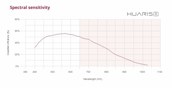
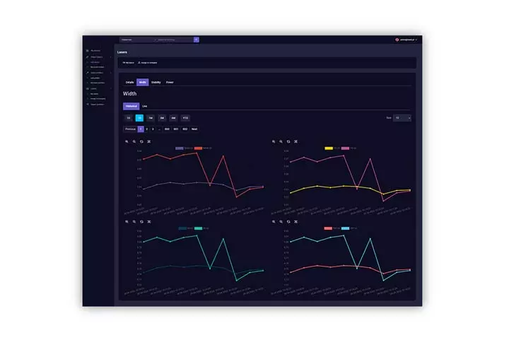
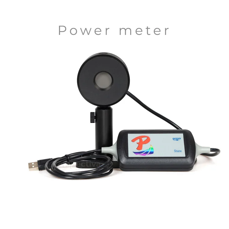
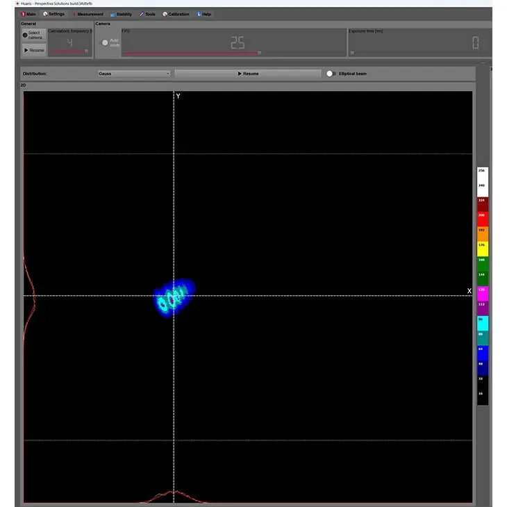
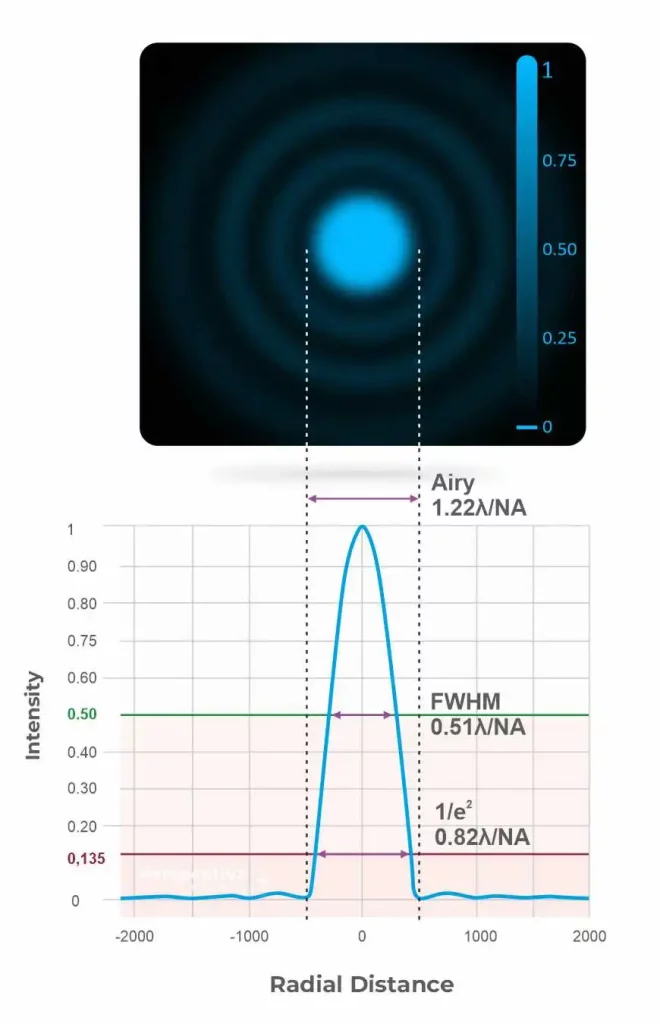
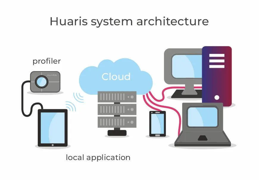
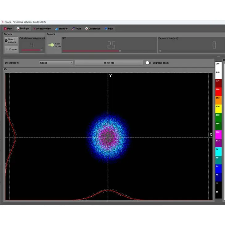
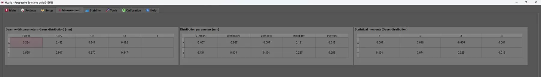
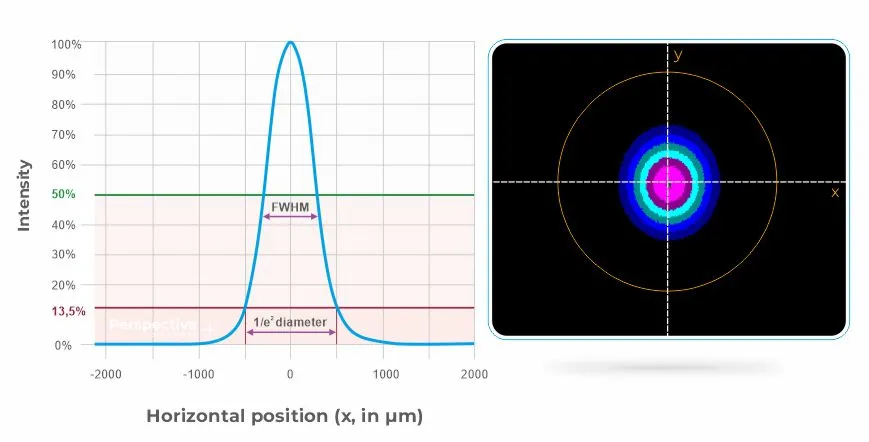
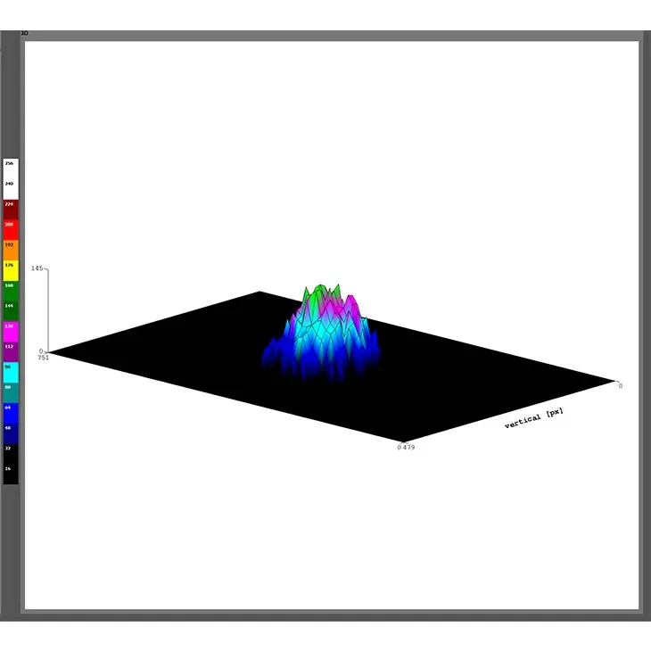
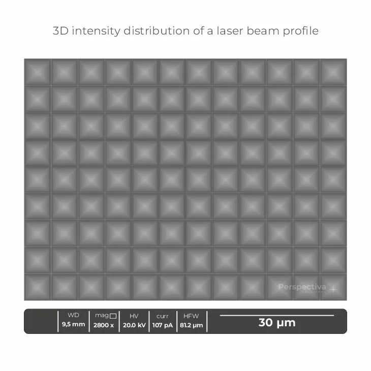
Moreover, a specific equipment, e.g. Huaris laser beam profilers, in the laser examination has to be used, parameters recorded and non-editable reports generated.
Identification, traceability and logging are all important aspects of managing the quality and safety of laser systems.
Identification: This refers to the process of identifying the specific laser system, as well as its components and accessories, by using unique identification numbers or codes. This can include serial numbers, model numbers, and other types of identification codes. Identification allows for the laser system to be tracked and traced throughout its life cycle and can be useful for troubleshooting and maintenance purposes.
Traceability: This refers to the ability to trace the history of a laser system, including its components and accessories, from the time of manufacture to the present. This can include information such as the date of manufacture, the supplier, the installation date, the maintenance history, and any repairs or upgrades that have been performed. Traceability is important for ensuring that the laser system has been properly maintained and for identifying any issues that may have arisen during its life cycle.
Logging: This refers to the process of keeping detailed records of the operation and maintenance of a laser system. This can include information such as the laser’s power, beam width, pointing stability, and other parameters, as well as information about maintenance and repairs that have been performed. Logging is important for ensuring that the laser system is operating within its specified parameters and for identifying any issues that may have arisen during its operation.
All three of these practices can be implemented by using software systems, manual records or a combination of both. These practices can be essential for ensuring the quality, safety, and regulatory compliance of laser systems. They also help in case of an incident, as it allows an investigation and understanding of what went wrong and how to prevent it from happening again.
In the Huaris Laser Cloud each laser is given its unique identification number (ID) which allows clear fulfillment of the identification, traceability and logging requirement as the measurement data is stored over a longer period of time and the reports can be generated at any time.
Laser reporting tools are software programs or applications that are used to collect, analyze and report on data from laser systems. These tools can be used to monitor the performance of laser systems in real-time, and can also be used to generate reports on the laser’s performance over time.
Some examples of laser measurement and reporting tools include:
Beam profilers: These are specialized tools that are used to measure the intensity distribution of a laser beam. They can be used to generate reports on the laser’s beam width, pointing stability, and other parameters.
Power meters: These are tools that are used to measure the power of a laser beam. They can be used to generate reports on the laser’s power, and also to detect any changes in the power over time.
Data acquisition software: This software is used to collect and store data from laser systems. It can be used to collect data on the laser’s power, beam width, pointing stability, and other parameters, and can also be used to store this data for later analysis.
Data analysis software: This software is used to analyze data from laser systems. It can be used to detect patterns or trends in the data, and can also be used to generate reports on the laser’s performance over time.
Remote monitoring software: This software allows remote monitoring and control of laser systems, it can also allow the collection and analysis of data from the laser remotely, which can be useful for maintenance and troubleshooting purposes.
Statistical process control (SPC) software: These software allow the use of statistical methods to monitor and control the quality of the laser system over time, it can help to detect patterns and trends that may indicate a problem with the laser and schedule maintenance accordingly.
These laser reporting tools can be beneficial for ensuring the quality, safety, and regulatory compliance of laser systems. They can also help to identify problems with laser systems before they lead to a failure.
Preventive and predictive maintenance are two types of maintenance strategies that can be used to keep laser systems in good working condition and minimize downtime. The specific preventive and predictive maintenance tasks will depend on the type of laser, its usage and the environment it is operating in. Additionally, the maintenance schedule should be adjusted accordingly to the laser’s usage, age, and environment.
Preventive maintenance: This is a regular maintenance schedule that is designed to identify and correct potential problems before they lead to a failure or a significant reduction in the performance of the laser. Preventive maintenance can include tasks such as cleaning and aligning the laser’s optics, replacing worn or damaged components, and performing calibration, alignment, cleaning and performance tests.
Predictive maintenance: This is a more advanced maintenance strategy that uses data and analysis to predict when a failure or a significant reduction in performance is likely to occur, and schedule maintenance accordingly. Predictive maintenance can include tasks such as monitoring the laser’s power, beam width, and pointing stability, as well as analyzing data from the laser’s control systems to detect patterns or trends that may indicate a problem with the laser.
Both preventive and predictive maintenance are essential for ensuring the reliability and performance of laser systems. Preventive maintenance can help to prevent unexpected failures and reduce downtime, while predictive maintenance can help to identify potential problems before they lead to a failure, reducing the need for expensive repairs and downtime.
Predictive maintenance is a strategy that uses data and analysis to predict when a failure or a significant reduction in performance is likely to occur, and schedule maintenance accordingly. This can be accomplished by monitoring the laser’s performance and using data analysis techniques to detect patterns or trends that may indicate a problem with the laser.
Power drift: A gradual decrease or increase in the laser power over time can indicate a problem with the laser or its optics.
Beam pointing stability: Changes in the position or alignment of the laser beam over time can indicate a problem with the laser’s alignment or vibrations in the environment
Mode quality: Changes in the transverse mode of the laser beam over time can indicate a problem with the laser’s optics or temperature.
Spectral properties: Changes in the wavelength or bandwidth of the laser beam over time can indicate a problem with the laser’s components or temperature.
Coherence: Changes in the spatial and temporal coherence of the laser beam over time can indicate a problem with the laser’s optics or temperature.
Temperature: A change in the laser’s temperature can indicate a problem with the cooling system, which can lead to a failure or a significant reduction in performance.
Typically a number of parameters is observed to deliver a valuable suggestion about the maintenance need and timing. These parameters have to be checked at a specific moment in time. They have to be monitored in the long term to detect time trends and estimate the time when the threshold of a specific parameter will be reached. It is worth mentioning that such a strategy allows detection when the problem might come, providing a first on the market tool to properly plan maintenance works.
It’s important to note that while monitoring these parameters, it’s possible to predict when a failure or a significant reduction in performance is likely to occur, it’s not always possible to predict with certainty when a failure will occur. However, by monitoring the laser’s performance and using data analysis techniques to detect patterns or trends, it’s possible to schedule maintenance at the right time, which can reduce the risk of failure and downtime.
Using AI in laser diagnostics can be an effective way to implement preventive maintenance for industrial applications because it allows for the real-time monitoring and analysis of laser performance data. This can help to detect patterns or trends that may indicate a problem with the laser before it leads to a failure or a significant reduction in performance.
Real-time monitoring: AI algorithms can process large amounts of data in real-time, which allows for the continuous monitoring of the laser’s performance. This can help to detect problems before they lead to a failure or a significant reduction in performance. In Huaris it takes only tens of milliseconds to process measurement data by AI.
Data analysis: AI algorithms can analyze the data collected from the laser and detect patterns or trends that may indicate a problem with the laser. This can help to predict when a failure or a significant reduction in performance is likely to occur, and schedule maintenance accordingly.
Adaptability: AI algorithms can be trained and adapt to different laser types, environments and usage patterns. This allows for the development of a customized solution for each industrial application, which can be crucial for their reliability and performance.
Automation: AI-based systems can automate the monitoring and analysis of laser performance data, which can reduce the need for manual intervention and increase the efficiency of the maintenance process. It also allows implementation of laser beam monitoring in a great scale, e.g. in industrial applications.
Cost-effective: By detecting problems before they lead to a failure or a significant reduction in performance, AI-based systems can help to reduce the need for expensive repairs and downtime, which can be a cost-effective solution for industrial applications.
It’s worth noting that AI-based solutions are not a replacement of human expertise but rather an aid to it, and it’s important to have a team of experts who can interpret the results and take the appropriate actions. Additionally, AI-based systems may require significant computational resources and expertise for development, deployment and maintenance.
Automating laser beam monitoring can be done by using a combination of hardware and software tools.
Hardware setup: This includes setting up laser beam monitoring equipment, such as beam profilers, power meters, and other types of detectors, as well as other related equipment like cameras, mirrors, lenses and so on. Perspectiva offers HUARIS beam profiles and also dedicated sensors tailored for a specific laser system.
Data acquisition: This includes configuring the equipment to collect data from the laser beam, such as power, beam width, pointing stability, and other parameters. This data can be collected in real-time or at regular intervals, depending on the specific requirements of the application.
Data storage: This includes storing the data collected from the laser beam in a computer, cloud server, or other types of storage devices. This allows for the data to be analyzed later and provides a historical record of the laser beam parameters.
Data analysis: This includes using software tools to analyze the data collected from the laser beam. This can include using mathematical algorithms or AI-based techniques to detect patterns or trends in the data that may indicate a problem with the laser.
Automated actions: This includes configuring the system to take automated actions in response to the results of the data analysis. This can include sending an alarm or email, adjusting the laser parameters, scheduling maintenance or shutting down the laser if necessary.
Remote access: This includes allowing remote access to the system, so that the data can be analyzed and the laser can be controlled from a remote location. This can be done by using web-based interfaces which are operating system agnostic.
It’s worth noting that automating laser beam monitoring requires a solid understanding of the laser system and the process, as well as the ability to program and configure the hardware and software components of the system. Additionally, the system should be regularly checked, calibrated and maintained to ensure it’s providing accurate data and the system is safe. All that can be achieved thanks to a proper IT system backed by AI and backed by high quality profilers and sensors.
Trends in the laser beam parameters refer to the changes or variations that occur in the laser beam over time. By monitoring the laser beam parameters over a period of time, it is possible to detect and analyze these trends, which can provide valuable information about the performance of the laser and the consistency of the process. Trends monitoring is a critical tool in laser preventive maintenance. For instance, observing the laser beam position over time allows detection of drift caused e.g. by optomechanics instabilities or by a thermal drift. On the other hand detection and quantitative monitoring of trends in the diffraction patterns allows estimation of risk of the laser corruption or allows planning maintenance actions in the right time allowing maximization of the beam availability.
Power drift: This refers to a gradual decrease or increase in the laser power over time. Power drift can be caused by factors such as changes in the laser’s temperature or aging of the laser’s components. For example a laser diode.
Beam pointing stability: This refers to changes in the position or alignment of the laser beam over time. Beam pointing stability can be affected by factors such as vibrations or changes in the alignment of the laser’s optics.
Beam width: Beam width can fluctuate over time if the optical system gets misaligned or due to thermal effects. Detecting this trend is vital to many processes. One good example could be using femtosecond lasers in the medical procedure of cataract removal. In such an operation a human eye retina is cut by a femtosecond laser to allow removal of a natural lens. The size of a spot has a direct impact on the size of a scar forming after the procedure. This scar later scatters the light causing side effects. The relation is: the greater focal spot, the greater the risk of the side effects. Another interesting example could be CNC laser-equipped mills which cut diamonds. Obviously, no one would like to lose more of this precious material than needed. Also if the size of the spot is too big thermal effects might cause the diamond uncontrolled break. Thus monitoring of beam width is of great interest.
Example of changes in the beam width of a test laser monitored in the Huaris Laser Cloud is presented in the image below.
Mode quality: This refers to changes in the transverse mode of the laser beam over time. Mode quality can be affected by factors such as changes in the temperature or alignment of the laser’s optics.
Spectral properties: This refers to changes in the wavelength or bandwidth of the laser beam over time. Spectral properties can be affected by factors such as aging of the laser’s components or changes in the temperature. It is well known that thermal drift has to be addressed by a proper heat management in many lasers to secure stable wavelength generation.
Coherence: This refers to changes in the spatial and temporal coherence of the laser beam over time. Coherence can be affected by factors such as changes in the temperature or alignment of the laser’s optics.
By detecting and analyzing trends in the laser beam parameters, it is possible to identify potential problems with the laser or its optics and take corrective actions before they lead to a significant reduction in the process quality or a failure of the equipment. It also helps in understanding the laser beam’s overall behavior over time, which can be very useful in the process quality management and prediction of future maintenance needs.
Measuring the beam width of a laser over a long period of time can provide valuable information about the stability and performance of the laser, as well as the consistency of the process. There are several different methods and parameters that can be used to measure the beam width of a laser over a long period of time, such as:
Continuous monitoring: One approach is to continuously monitor the beam width using a beam profiler, a power meter, or other types of detectors. This can provide real-time data about the beam width and allow for the detection of any variations or changes that may occur.
Time-series measurements: Another approach is to take periodic measurements of the beam width at regular intervals, such as every hour or every day. This can provide a record of the beam width over time and allow for the detection of any trends or patterns that may occur.
Long-term data storage: It is important to store the data collected over the long run for further analysis, this data can be stored in a computer, a cloud server or other types of storage devices. This allows for the data to be analyzed later and provides a historical record of the beam width.
Statistical analysis: The data collected over the long run can be analyzed using statistical methods to identify any patterns or trends in the beam width. This can provide valuable information about the stability and performance of the laser over time.
It’s worth noting that the choice of method and the specific parameters used to measure the beam width will depend on the specific requirements of the application and the type of laser. Additionally, a well-calibrated and well-designed system is needed to accurately measure these parameters over a long period of time, without any drift or changes in the system.
Measuring the laser power over a long period of time can provide valuable information about the stability and performance of the laser, as well as the consistency of the process. There are several different methods and parameters that can be used to measure the laser power over a long period of time, such as:
Continuous monitoring: One approach is to continuously monitor the laser power using a power meter or other types of detectors. This can provide real-time data about the laser power and allow for the detection of any variations or changes that may occur.
Time-series measurements: Another approach is to take periodic measurements of the laser power at regular intervals, such as every hour or every day. This can provide a record of the laser power over time and allow for the detection of any trends or patterns that may occur.
Long-term data storage: It is important to store the data collected over the long run for further analysis, this data can be stored in a computer, a cloud server or other types of storage devices. This allows for the data to be analyzed later and provides a historical record of the laser power.
Statistical analysis: The data collected over the long run can be analyzed using statistical methods to identify any patterns or trends in the laser power. This can provide valuable information about the stability and performance of the laser over time.
Comparison to specifications: By comparing the measured laser power to the laser’s specifications, it’s possible to detect any variations or changes that may occur and take corrective actions before they lead to a significant reduction in the process quality or a failure of the equipment.
It’s worth noting that the choice of method and the specific parameters used to measure the laser power will depend on the specific requirements of the application and the type of laser, and also the power measurement system should be calibrated and stable over time to provide accurate measurements. Additionally, the environment and temperature can affect the power measurements, so it’s important to consider these factors when monitoring the laser power over a long period of time.
Diffraction patterns refer to the patterns that are formed when a laser beam passes through an aperture. These patterns are a result of the diffraction of light, which is a fundamental, non-avoidable physical phenomenon.
When a laser beam is passed through an aperture or reflected by a mirror, the diffraction of light causes the beam to spread out and form a pattern of light and dark regions. These regions are known as diffraction orders, and the intensity of the light in each region is determined by the size of the aperture and the wavelength of the light. The shape of the pattern is also affected by the distribution of the intensity on the laser beam and by the shape of the aperture.
Example diffracted beam is shown in the picture below. In this case it is linear diffraction on the Gaussian beam presented in the Huaris profiling software local application.
Airy disk: This is the central bright spot formed by the diffraction of light within the beam waist. The size of the Airy disk is determined by the wavelength of the light and the numerical aperture (NA) of the lens or mirror system.
Airy rings: These are the series of concentric bright and dark regions that surround the Airy disk. The intensity of the light in each ring is determined by the size of the aperture and the wavelength of the light.
Diffraction spikes: These are the bright lines that extend outward from the Airy disk. They are caused by the diffraction of light at the edges of the aperture or mirror.
Diffraction on the edges of optical elements: These are diffraction effects occurring when the laser beam is deflected and/or reflected on the edge of an optical element. E.g. it could be a lens or a mirror. Typically this phenomenon can be observed when the optical setup gets misaligned.
Diffraction on dust: This is a situation when the laser beam travels through the dirty optical elements. The particles of dust will cause tiny interference patterns and will damage the beam quality. If the intensity of the laser beam is high the dust may also absorb the light making it easier to damage the optical element that it sits on.
Diffraction on rough surfaces: If the surface of a mirror or of the lens is not smooth then it may also cause the diffraction of the laser beam.
The diffraction patterns can be observed in the laser beam profile by using a beam profiler or other types of detectors that can measure the intensity distribution of the beam. Understanding these diffraction patterns can be useful in assessing the quality of the laser beam, and can also be used to optimize the laser beam for specific applications.
It’s worth noting that diffraction patterns are dependent on the optical system and the wavelength of the laser, and can also be affected by other factors such as aberrations or the presence of dirt or dust on the optics.
The patterns are observed in Huaris in the long term and the user obtains notification when they are detected and when the trend in their area is observed.
Another key feature of the Huaris Cloud is the possibility to monitor all key laser beam parameters measured with the beam profiler in the long term.
Laser beam processing is a powerful technique used in a variety of materials processing applications, including cutting, welding, drilling, and surface modification. In this article, we will explore the different ways in which laser beams can be used for materials processing, and discuss the advantages and limitations of each approach. We will also examine the factors that influence the effectiveness of laser beam processing, such as laser power, beam profile, wavelength, and pulse duration.
Additionally, we will discuss the importance of laser beam profiling in materials processing, and how accurate characterization of laser beams can help to optimize process parameters and improve the quality and efficiency of materials processing operations. Whether you are a enginer, researcher, laser manufacturer, or simply interested in the world of lasers, understanding the use of laser beams in materials processing is essential for achieving optimal results and unlocking the full potential of laser technology.
Laser beams are widely used in materials processing due to their ability to deliver high energy, high power, and highly focused beams of light to a specific location. Additionally, it is relatively easy to manipulate the amount of energy deposited in the interaction area on the target to change the amount of the removed material or adapt to the thickness of the metal when welded. Also the position of the beam can be changed easily during the process. When compared to CNC machines, the laser does not use any tool that removes the desired material. Instead, a light beam is used and, obviously, the light does not wear as mechanical tools do. Due to this fact lots of cost can be saved on tooling.
In the medical applications there are numerous advantages, too. Using the laser beam that e.g. cuts the tissue does not require any physical contact of the medical device with the patient making the device highly aseptic.
Cutting: Lasers can be used to cut a wide range of materials, from metals and plastics to ceramics, glass or even diamonds. The high-energy laser beam melts or vaporizes the material, creating a clean, precise cut with minimal heat-affected zone.
Welding: Lasers can be used to weld a wide range of materials, including metals, plastics, and ceramics. The laser beam melts the material, creating a weld that is strong and has minimal distortion.
Drilling: Lasers can be used to drill small, precise holes in a wide range of materials, including metals, plastics, and ceramics. The laser beam melts or vaporizes the material, creating a clean, precise hole.
Surface modification: Lasers can be used to change the surface properties of materials, such as surface hardening, surface cleaning, and surface texturing. The laser beam can be used to heat the surface, creating a change in the surface micro or nanostructure.
3D printing: Lasers can be used to fuse powders or melt plastics to create 3D structures. The laser beam is used to melt or fuse the material, layer by layer, to create the final 3D structure. This process is often called: sintering.
Marking and engraving: Lasers can be used to mark or engrave a wide range of materials, including metals, plastics, and ceramics. The laser beam can be used to remove or change the surface color of the material, creating a permanent mark or engraving.
Surface cleaning: Various surfaces can be cleaned using lasers. E.g. Historical artifacts can be renovated using pulsed lasers as it was done by the scientific team of Institute of Optoelectronics, Military University of Technology at Wawel castle in Cracow.
A diffraction-limited focal spot refers to the smallest spot that can be formed by a laser beam using a lens or a mirror system. The size of this spot is determined by the diffraction of light, which is a fundamental physical phenomenon that occurs when light passes through an aperture or is reflected by a mirror.
The size of the diffraction-limited focal spot can be described by the Airy disk, which is the pattern formed by the superposition of the diffraction patterns produced by the individual points in the aperture of the lens or mirror. The size of the Airy disk is determined by the wavelength of the light and the numerical aperture (NA) of the lens or mirror system. The smaller the wavelength and the NA, the smaller the diffraction-limited focal spot will be.
It’s important to note that the diffraction-limited focal spot is the smallest spot that can be achieved using a lens or mirror system, but there are other factors that can affect the size of the focal spot in practice. For example, aberrations in the lens or mirror system, or the presence of dirt or dust on the optics can cause the focal spot to be larger than the diffraction limit. Additionally, thermal effects can also cause the focal spot to change in size over time.
A diffraction-limited focal spot is important in many applications that require high-resolution imaging, such as microscopy, or high-precision material processing. In these applications, a small focal spot can provide a high intensity at the focal point, which can increase the resolution and precision of the process.
Imagine your collimated laser beam has 1/e2 diameter D. It passes a lens with a focal length f and has wavelength lambda. In this case the smallest possible size of the focal spot is given by the formula:
This is also called Airy disk size.
It is shown in the graphics below
Please, note that the diffraction-limited focal spot size can be defined as:
NA is a parameter defining an optical system that the light passes through and it is named: Numerical Aperture. In the very advanced optical systems it is possible to tune NA to the level that effectively the focal spot will be smaller than the diffraction limit of a regular setup. This is a method employed in the lithography systems which are used to produce microprocessors. In these setups excimer lasers are used to produce structures much smaller than their wavelength.
.
Beam divergence: An increase in beam divergence will cause the focal spot to be larger and less intense. This can result in a reduction of resolution and precision in material processing. Also if the ablation is the main mechanism, then its efficiency may be reduced (e.g. in marking applications).
Beam pointing stability: A lack of beam pointing stability can cause the focal spot to move around, making it difficult to maintain a consistent focus on the material. This can lead to variations in the process parameters and a reduction in precision.
Beam mode quality: A low-quality beam mode, such as a high-order transverse mode, can cause the focal spot to be uneven and have a non-uniform intensity distribution. This can lead to variations in the process parameters and a reduction in precision.
Spatial and temporal coherence: A low coherence can cause the focal spot to be larger and less intense, and can also affect the stability of the process. It can also affect the ability of the laser to focus the beam to a small spot, and the ability to create interference patterns.
Power distribution: A non-uniform power distribution can cause the focal spot to be uneven and have a non-uniform intensity distribution. This can lead to variations in the process parameters and a reduction in precision.
Spectral properties: Spectral properties such as a broad spectrum, can cause the focal spot to be larger and less intense, and can also affect the stability
Aberrations of the optical systems: imperfection of the optical systems used to focus the beam will increase the size of the focus and will scatter the power over a greater area. This phenomenon may result in the reduction of process precision or loss of imaging resolution.
And this image shows spherical aberration, which is very common in setups where the laser beam is focused by only one (especially spherical) lens:
To conclude, it is always true that the laser beam quality is critical from the perspective of the process where it is being used. It has to be monitored and the maintenance works should be planned to keep it as good as possible. One good example could be using femtosecond lasers in the medical procedure of cataract removal. In such an operation a human eye retina is cut by a femtosecond laser to allow removal of a natural lens. The size of a spot has a direct impact on the size of a scar forming after the procedure. This scar later scatters the light causing side effects. The relation is: the greater focal spot, the greater the risk of the side effects. This example very clearly presents how important it is to take care of the laser beam quality.
Laser beam monitoring is essential in process quality management as it allows for real-time analysis of the laser beam properties, such as beam profile, power, and energy, ensuring that the laser process is operating optimally and within specified parameters. By continuously monitoring the laser beam, operators can detect potential issues early, allowing for quick corrective action and minimizing the risk of product defects or downtime. Furthermore, laser beam monitoring allows for accurate characterization of the laser beam, which is crucial for process optimization and control. Ultimately, laser beam monitoring is essential for ensuring high-quality products and optimizing manufacturing processes in industries such as medical, aerospace, and automotive. Huaris AI Cloud is predictive maintenance for laser systems.
Process control: By continuously monitoring the laser beam parameters, such as power, beam width, and pointing, it is possible to detect and correct any variations or changes that may occur, which can affect the process quality. This can help to ensure that the process is consistent and produces parts with the desired quality.
Safety: By monitoring the laser beam, it is possible to detect any unexpected changes in the beam that could indicate a problem with the laser or its optics. This can help to prevent damage to the equipment and potential safety hazards.
Efficiency: By continuously monitoring the laser beam, it is possible to detect any variations or changes in the beam that may affect the efficiency of the process. For example, a decrease in the beam power can result in a decrease in the cutting speed, or an increase in the beam pointing stability can result in an increase in the cutting precision.
Predictive/preventive maintenance: By monitoring the laser beam over time, it is possible to detect any changes or variations that may indicate a problem with the laser or its optics. This can help to identify potential issues before they lead to a failure or a significant reduction in the process quality.
Traceability: By monitoring the laser beam, it is possible to collect data about the process and the beam parameters, which can be used to trace potential changes back if the quality assurance needs to check the reasons of the process malfunction.
Numerous process parameters can be affected if the laser beam does not meet quality acceptance criteria. Huaris Cloud is the first solution of this kind to monitor the beam parameters over a long period of time and supports the laser owner in automatic detection of the laser misbehavior.
Evaluating the beam width of a laser is an important step in characterizing its performance and determining its suitability for a particular application.
Full-width-at-half-maximum (FWHM): This is the width of the beam at a point where the intensity is half the peak intensity. It is commonly used as a measure of the beam width for laser beams with Gaussian intensity distributions.
1/e² radius: This is the radial distance from the center of the beam at which the intensity has dropped to 1/e² (about 13.5%) of the peak intensity. The 1/e² radius can be used as a measure of the width of the beam at a particular point and is commonly used to calculate the M² parameter.
Beam diameter: This is a measure of the width of the laser beam at a particular point, and can be defined in many ways, such as the D4σ, D9σ, D15σ etc.
Especially, for the beam with irregular shape, a statistical approach is preferred. The most popular being: D4σ, or simply: 4σ meaning: 4 times standard deviation of the Gaussian statistical distribution.
Gaussian fit: This method consists in fitting the measured beam profile to a Gaussian function, and extracting the parameters of the fit such as the beam waist and the divergence.
Top-hat fit: This method consists in fitting the measured beam profile to a Top-hat function, and extracting the parameters of the fit such as the beam diameter and the flat-top radius.
Check the possibilities of profiling the laser beam using Huaris Profiling Software. The definition of the beam width parameters of the Gaussian distribution of the intensity distribution across the beam is shown in the graph below:
The method used to evaluate the beam width will depend on the type of laser and the characteristics of the beam, as well as the specific requirements of the application. For example, a Gaussian fit may be more appropriate for a laser with a Gaussian intensity distribution, while a Top-hat fit may be more appropriate for a laser with a non-Gaussian intensity distribution. Additionally, a well-calibrated and well-designed system is needed to accurately measure these parameters.
Please mind, that beam width parameter is probably the most common metrics used to characterize the beam of a laser. For this reason it has been standardized and described in ISO 11146 norm.
In the mentioned standard the measurement of the elliptical beams has been also defined. The methodology of measuring such beams used in the Huaris software has been directly implemented according to this definition.
Beam width monitoring is a critical aspect to control the quality of the process conducted by the laser.
There are several different methods that can be used to measure the beam width of a laser, including:
1. Knife-edge scan: This method consists of moving a knife edge across the beam and measuring the intensity of the light transmitted through the edge. This can be done by using a photodiode or a camera. The data obtained from the knife-edge scan can be used to calculate the beam width by analyzing the intensity profile of the beam.
2. Beam profiler: A beam profiler is a device that captures an image of the beam profile and then analyzes the image to determine the beam’s characteristics. Beam profilers can be used to measure the beam width by analyzing the intensity distribution of the beam. They can be used to measure both the spatial and temporal profile of the beam.
3. Power meter: A power meter is a device that measures the power of a laser beam. It can be used to measure the beam width by measuring the power of the beam at different points along the beam axis. The data obtained from the power meter can be used to calculate the beam width by analyzing the power distribution of the beam.
4. Interferometry: This method consists in using an interferometer to split the laser beam into two beams and then recombining them to create an interference pattern. The interference pattern can be used to determine the phase and amplitude of the two beams, and from that, the beam width can be inferred.
5. Far-field measurement: It consists in measuring the beam’s intensity distribution in the far field. The far-field measurement can be done by using a camera or a detector array, and it can provide information about the beam’s divergence and other parameters that can be used to infer the beam width. In the far-field measurement the profiler is used. To achieve far-field image of the beam most commonly an additional focusing lens is used. An example of a measurement setup is shown in the graph below:
In such a setup a detector array of a profiler is positioned in the beam waist.
Each method has its own advantages and limitations. For example, knife-edge scan and beam profiler are easy to use and can provide a lot of information about the beam profile, but they can be affected by the alignment of the system. Interferometry is a precise method but is more complex to set up and use.
Array-based detectors are considered as one of the best options for laser beam characterization because they offer several advantages over other types of detectors:
High spatial resolution: Array-based detectors, such as CCD or CMOS cameras, have a large number of individual detector elements that are closely spaced together. This allows for a high spatial resolution, which can be useful for measuring small features or variations in the beam profile.For example, Huaris Five profiler has a pixel size of only 2.2 micrometer.
High dynamic range: Array-based detectors can measure a wide range of intensities, from very low levels to very high levels. This makes them well-suited for measuring laser beams with a wide range of power levels or for measuring beams with both high and low intensity regions.
High speed: Array-based detectors can acquire images at high speeds, which can be useful for measuring rapidly changing beams or for measuring the beam’s temporal characteristics. Nowadays CMOS and CCD cameras are able to acquire the intensity map much faster than typically the changes in its distribution in the beam happen allowing real-time monitoring of the beam quality.
High signal-to-noise ratio: Array-based detectors typically have a low noise floor, which allows them to measure weak signals with a high degree of accuracy.
Versatility: Array-based detectors can be used in a wide range of applications, from simple measurements of the beam profile to more advanced measurements of the beam’s temporal and spatial characteristics.
Cost-effective: Array-based detectors, such as CCD or CMOS cameras, can be less expensive than other types of detectors and they are widely available.
It’s worth noting that while array-based detectors are widely considered as one of the best options for laser beam characterization, other types of detectors can also be used, depending on the specific requirements of the application. Additionally, the performance of array-based detector can be affected by the optics, electronic noise, and the detector’s sensitivity.
When discussing array detectors it is necessary to mention the electronics and software that work with it. CMOS and CCD cameras due to their technological maturity are capable of working with high-level and very advanced software. As a result, a lot of new metrological functionalities can be implemented which is very often not possible or extremely difficult with other methods and equipment. As an example Huaris architecture can be presented: a local detector with electronics is physically connected with a local computer which hosts a local application allowing monitoring of the beam parameters at site. The local application also works as a communication hub feeding the data to the remote cloud server. The Huaris Cloud stores the data in the long term, analyzes the measurement results using artificial intelligence and helps to interpret them.
Laser beam quality evaluation is the process of measuring and analyzing the characteristics of a laser beam to determine its suitability for a particular application. This process involves measuring various parameters of the beam, such as its power, spatial and temporal coherence, beam width, divergence, and shape. Evaluating the laser beam quality is essential for ensuring optimal performance, achieving desired outcomes, and reducing the risk of errors or defects.
Laser beam quality is a critical parameter that can significantly impact the performance of laser systems in a variety of applications, including industrial, medical, and scientific. In this article, we will explore the different methods for evaluating laser beam quality, including M² measurements, beam divergence, and beam propagation ratio, and explain the advantages and limitations of each approach. We will also discuss the factors that can affect laser beam quality, such as beam profile, wavelength, and mode structure, and their impact on laser performance. Additionally, we will examine the importance of proper alignment and calibration in achieving accurate measurements of laser beam quality.
M² (pronounced “M squared”) is a dimensionless parameter that characterizes the beam quality of a laser. It is defined as the ratio of the actual beam waist (w0) to the diffraction-limited beam waist (w0,DL) at a particular point in space. The diffraction-limited beam waist is the smallest spot size that can be obtained with a perfect, diffraction-limited optical system, assuming a Gaussian beam at the same wavelength and divergent angle. A lower M² value indicates a higher beam quality.
When M² is equal to 1, then the beam is diffraction limited, it has smallest possible divergence and smallest achievable focal spot. Typically, real-life beams have M² in the range of 1.2-1.4. M² is never smaller than 1.
M² is commonly used to quantify the quality of laser beams, especially for high-power industrial lasers, and laser amplifiers, where the beam quality is crucial to the process or system performance.
It can be determined by measuring the beam size at different positions along the beam’s axis and then plotting these values as a function of position. A Gaussian fit can then be applied to these data to extract the beam waist and the divergence. By comparing these values with the values of an ideal Gaussian beam with the same wavelength and divergence, the M² can be calculated.
A common method to measure the M² is by using a beam profiler. A beam profiler is a device that captures an image of the beam profile and then analyzes the image to determine the beam’s characteristics. Here you can check examples of Huaris laser beam profilers.
Other methods include knife-edge scans and the use of beam diagnostic equipment like the far-field measurement.
It is worth noting that the M² is a single-valued parameter and it can be affected by the measurement position and the measurement conditions. It is also dependent on the wavelength and divergence. The higher the divergence of the beam, the lower the M² value.
Beam width is a measure of the size of a laser beam at a particular point, such as the beam waist or the focus spot. The beam width can be characterized by several different parameters, including:
Beam waist (w0): This is the point of the smallest spot size along the beam axis. The beam waist is often used as a measure of the overall quality of the beam and is commonly used to calculate the M² parameter.
1/e² radius: This is the radial distance from the center of the beam at which the intensity has dropped to 1/e² (about 13.5%) of the peak intensity. The 1/e² radius can be used as a measure of the width of the beam at a particular point and is commonly used to calculate the M² parameter.
Full-width-at-half-maximum (FWHM): This is the width of the beam at a point where the intensity is half the peak intensity. It is commonly used as a measure of the beam width for laser beams with Gaussian intensity distributions.
Beam diameter: This is a measure of the width of the laser beam at a particular point, and can be defined in many ways, such as the D4σ, D9σ, D15σ etc.
Especially, for the beam with irregular shape, a statistical approach is preferred. The most popular being: D4σ, or simply: 4σ.
It’s worth noting that different beam width parameters may be more appropriate for different types of lasers or applications. For example, the 1/e² radius is commonly used for laser beams with Gaussian intensity distributions, while the FWHM may be more appropriate for laser beams also with non-Gaussian intensity distributions. Additionally, a well-calibrated and well-designed system is needed to accurately measure these parameters.
The definition of most common beam width parameters (FWHM and 1/e2) is presented in the graph below:
Please mind, that beam width parameter is probably the most common metrics used to characterize the beam of a laser. For this reason it has been standardized and described in ISO 11146 norm.
In the mentioned standard the measurement of the elliptical beams has been also defined. The methodology of measuring such beams used in the Huaris software has been directly implemented according to this definition.
Beam width monitoring is a critical aspect to control the quality of the process conducted by the laser.
Beam pointing refers to the ability of a laser to accurately point or direct its beam to a specific location or target. This is important in many applications, such as laser material processing, where the beam must be precisely focused on a specific location, or in laser communications or lidar, where the beam must be directed to a specific receiver.
Turbulence: deviations of the beam spatial position due to the change of the change of density of gasses that the beam propagates through.
To maintain accurate beam pointing, a variety of active or passive stabilization methods can be used. For example, a laser’s internal components can be actively cooled or temperature-controlled to reduce the effects of thermal expansion. Mechanical vibration isolation can be used to reduce the effects of external vibrations. And feedback control mechanisms can be used to monitor and adjust the laser’s internal components to ensure that the beam is pointing in the correct direction.
Additionally, the beam pointing can be measured by using beam profilers or quadrant detectors, which can detect a small shift in the beam position, and use the information to adjust the alignment accordingly.
Typically the profilers can offer higher accuracies of the measurements of the beam pointing stability. The animation below presents how the position of the beam is monitored in the Huaris local application.
Jitter refers to small, rapid fluctuations in a signal or a system’s performance. In the context of laser beam pointing, jitter refers to small, rapid fluctuations in the position of the laser beam. These fluctuations can be caused by a variety of factors, such as mechanical vibrations, temperature changes, or power fluctuations.
Temporal (or timing) jitter: This is the variation in the position of the beam over time. Essentially it refers to the situation, where each subsequent pulse should appear every specified period of time. However, in reality the consecutive pulses arrive sooner or later than expected. These deviations from expected arrival moments are called the timing jitter.
Jitter can be detrimental to many laser applications, particularly those that require precise beam pointing or alignment. For example, in laser material processing, jitter can cause the beam to move away from the intended target, leading to poor quality or incomplete processing. In laser communication or LIDAR, jitter can lead to poor signal quality, reducing the accuracy of the system.
To reduce jitter, the system must be designed with stability and mechanical vibration isolation in mind. Additionally, active or passive stabilization methods can be used to monitor and correct for jitter in real-time, for example, by using a feedback loop that adjusts the laser’s internal components to maintain accurate beam pointing.
Coherence is a fundamental property of laser beams that refers to the correlation between different parts of the light wave. There are two types of coherence: temporal coherence and spatial coherence.
refers to the correlation of the phase and frequency of the light wave at different points in time. A laser beam is said to be temporally coherent if the phase and frequency of the light wave is the same for all points in the beam over time. The temporal coherence of a laser can be described by the coherence time, which is the length of time over which the phase and frequency of the light wave remains constant. High temporal coherence is important in applications such as interferometry, where the phase and frequency of the light wave must remain constant over time in order to generate accurate measurements.
refers to the correlation of the phase and frequency of the light wave at different points in space. A laser beam is said to be spatially coherent if the phase and frequency of the light wave is the same for all points in the beam. The spatial coherence of a laser can be described by the coherence length, which is the distance over which the phase and frequency of the light wave remains constant. High spatial coherence is important in applications such as laser material processing, where the laser beam must be focused to a very small spot, and maintain that focus over a long distance.
Within the spatial coherence the longitudinal and transversal spatial coherence is distinguished to stress direction in space over which the coherence is analyzed.
is a measure of the degree of spatial coherence of a laser beam, it can be defined as the distance over which the light waves’ phase difference is less than 1 radian. It is a measure of the distance at which the phase of the light wave becomes random. It is a key parameter in many laser applications such as interferometry, holography and laser material processing.
It is worth noting that the coherence length and coherence time are inversely proportional to the spectral bandwidth of the laser, the narrower the bandwidth the longer the coherence length and time.
Power is a measure of the rate at which energy is transferred, and it is a fundamental physical quantity. In the context of lasers, power refers to the amount of energy per unit time that a laser can emit. The power output of a laser is typically measured in watts (W), milliwatts (mW), or microwatts (μW).
The power output of a laser is determined by the amount of electrical power that is supplied to the laser, as well as the efficiency of the laser’s optical system. The power output can be adjusted by adjusting the amount of electrical power that is supplied to the laser, or by adjusting the optical components of the laser’s system.
The power of a laser is one of its key parameters, as it affects the performance of the laser in various applications. For example, in laser material processing, a higher power laser can cut or weld thicker materials than a lower power laser, and in laser communication, a higher power laser can transmit a signal over a greater distance than a lower power laser.
It is also worth noting that the power distribution within the laser beam can also affect the performance of the laser, for example, a Gaussian power distribution is usually preferred for laser material processing as it provides a more symmetric and consistent heating of the material, while a top-hat power distribution is preferred for some optical micromachining processes as it provides a uniform and high intensity over a certain area.
Measuring laser beam parameters, such as power, beam width, and pointing, over a long period of time can help to ensure that the laser is operating within its desired specifications and to detect and correct any changes or variations that may occur.
Environmental monitoring: This approach employs consist in monitoring the environmental conditions that can affect the beam parameters, such as temperature, humidity, and vibrations. This data can be used to identify any correlation with variations in the beam parameters.
It’s important to note that long-term measurement of laser beam parameters requires a stable and well-calibrated system. The measurements must be conducted under controlled conditions, to avoid any environmental or external effects that can affect the results. Additionally, it’s recommended to use a combination of methods, as each one can provide specific information or can help to cross-validate the results.
Huaris Cloud is a first in the world, commercially available system allowing long-term monitoring of the laser beam parameters. It does not only store the data, render and analyze using AI. It also detects time trends in the monitored parameters and warns the laser user about its occurrence suggesting that some preventive maintenance action should be taken. Read more about it.
Laser beam profiling is an essential tool for measuring and analyzing the properties of laser beams. In this article, we will explore the concept of laser beam profiling and explain the importance of understanding the characteristics of laser beams. We will discuss the various methods used to measure and analyze laser beams, including the use of cameras, sensors, and software, and explain the advantages and limitations of each approach. Additionally, we will look at the different applications of laser beam profiling, from laser system design and manufacturing to scientific research and medical applications. Whether you are new to the world of lasers or a seasoned professional, understanding laser beam profiling is essential for achieving optimal laser performance and unlocking the full potential of laser technology.
A laser beam profile is a measurement of the intensity distribution of a laser beam at a particular point in space. The profile can be measured using a device called a laser beam profiler, which detects the light from the beam and creates a kind of a map of the intensity distribution in space. The profile of a laser beam can have different shapes, such as a Gaussian, Top-Hat, Lorentz or Bessel-like shape, depending on the characteristics of the laser and the optics used to shape the beam.
The image above presents an ideal, 2D Gaussian beam profile color using color map shown in the right part of the picture
The beam profile can also change over the distance, or along the beam propagation path, the most common example is beam divergence. The beam profile is important for many laser applications, as it determines the amount of energy delivered to a target, the size and shape of the laser’s focus spot, and the intensity and uniformity of the light at a given location
Both CMOS (complementary metal-oxide-semiconductor) and CCD (charge-coupled device) cameras can be used to measure laser beam profiles. These cameras are able to detect the light from the laser beam and create an image of the intensity distribution, which can be analyzed to determine the beam profile.
Both CMOS and CCD cameras work by converting light into electrical charges. In a CMOS camera, each pixel in the sensor has its own photodetector and amplifier, which converts light into an electrical signal. The signals from all the pixels are then read out and processed to create an image. CMOS cameras have several advantages, including low power consumption, high readout speed, and the ability to integrate other functions, such as image processing, on the same chip.
A CCD camera, on the other hand, works by accumulating charges generated by incoming photons on a semiconductor and readout by shifting it from one register to another. CCD cameras have been traditionally known for their high image quality and low noise, but modern CMOS cameras have closed the gap.
Both camera types can be used to measure laser beam profiles, but they have different characteristics that may make one better suited to a particular application. For example, CCD cameras are known for their excellent sensitivity and low noise, which make them well-suited for low-light applications. CMOS cameras, on the other hand, are known for their high readout speeds and low power consumption, which make them well-suited for high-speed applications. They are said also to be more resistant to damage from too high laser powers.
In either case, the camera’s image needs to be captured by a software that can process the image of the laser spot and determine the beam profile. The most common one used is the Gaussian fit on the image intensity.
The example of the image of the surface of the CMOS array is shown in the picture below. This image was acquired using SEM (Scanning Electron Microscope) to investigate pixels’ geometry. Each small square shown in the picture is a real light-sensitive detector, a pixel.
A laser beam profile can refer to the two-dimensional (2D) intensity distribution of a laser beam, or it can refer to the three-dimensional (3D) intensity distribution.
The 2D intensity distribution, also known as the transverse intensity distribution, is a measurement of the intensity of the laser beam at a particular point in space, such as at a focal point or a target. It shows how the intensity of the laser beam varies across the cross-sectional area of the beam.
The 3D intensity distribution, on the other hand, is a measurement of the intensity of the laser beam at multiple points in space and can provide a more complete picture of the beam’s characteristics. It describes how the intensity of the laser beam varies not only across the cross-sectional area but also along the beam’s axis, taking into account the beam divergence or focus point.
To measure 3D intensity distribution, a combination of methods can be used. For example, by measuring the intensity at multiple points in space by moving a sensor or the beam in a controlled manner, or by using a specialized imaging system, such as a Shack-Hartmann sensor or a scanning slit system. These methods can provide a more detailed and accurate characterization of the laser beam, which can be useful in applications such as laser material processing, where the 3D intensity distribution can affect the quality of the processed material.
Combining these images allows drawing “caustics” of the laser beam which is schematically shown in the picture below
Such a curve (caustics) allows e.g. to estimate one of the beam quality factors: M2.
There are various types of artifacts that can be present in a laser beam profile, depending on the specific characteristics of the laser and the measurement system being used. Some examples of common artifacts include:
This refers to any unwanted variations in the intensity of the laser beam, such as those caused by fluctuations in the power supply or temperature changes. Noise can make it difficult to accurately measure the beam profile and can appear as random variations in the intensity distribution.
This refers to the phenomenon of cutting off high intensity regions of the laser beam. It happens when the sensor used to measure the beam profile saturates, meaning it can’t detect the highest intensity regions of the beam. Clipping can lead to an underestimation of the true peak intensity of the beam.
This refers to the spreading of the beam due to the diffraction or reflection by any surfaces or materials in the beam path. Scattering can cause the beam to become distorted, leading to a change in the beam profile.
This can be caused by the optical components being not fully optimized for the laser wavelength and can lead to a non-uniform intensity distribution.
This can occur in the Shack-Hartmann sensor, for example. The sensor uses a lenslet array to sample the laser beam and compare it to a reference beam. If the reference beam does not match the characteristics of the laser beam being measured, it can lead to inaccuracies in the measured beam profile.
a very common problem in the laser systems is dust. It may appear on the optical elements. Then these small speckles may affect the laser beam quality causing diffraction on them but if the intensity of the beam increases the dust speckle may excessively absorb the radiation and transfer the heat to the mirror finally leading to its break.
It’s worth mentioning that Huaris Laser Cloud backed by the artificial intelligence detects dust in the beam fully automatically at the very early stage when the risk of damage of the optical components is low. It will warn the laser user and will advise cleaning the optical elements before they irreversibly get broken.
There are various kinds of diffraction that can be observed with laser beams. E.g. linear or circular – depending on the structure that the laser beam has encountered on its propagation path. Also the beam may encounter rounded edges, like a mirror edge. Then the resulting diffraction pattern will have a roundish shape.
In similar fashion to the dust detection our AI can also detect various kinds of diffraction patterns appearing very early. Often even before the human eye can recognize that and it will give a clear indication that something is going wrong with the laser. In this case Huaris Cloud will also advise you maintenance actions, e.g. checking the beam alignment.
Example diffracted beam is shown in the picture below. In this case it is linear diffraction on the Gaussian beam presented in the Huaris profiling software local application.
It is worth noting that these artifacts might not appear in all the measurements, also a well-designed and calibrated system can reduce these artifacts considerably.